ActorClass
ActorClass ActorClass2 {}
ActorRef
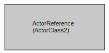
ActorClass ActorClass1 {
	Structure {
		ActorRef ActorReference: ActorClass2
	}
}
This chapter gives an overview over the ROOM language elements and their textual and graphical notation. The formal ROOM grammar based on Xtext (EBNF) you can find in the eTrice repository:
http://git.eclipse.org/c/etrice/org.eclipse.etrice.git/plain/plugins/org.eclipse.etrice.core.room/src/org/eclipse/etrice/core/Room.xtext
The actor is the basic structural building block for building systems with ROOM. An actor can be refined hierarchically and thus can be of arbitrarily large scope. Ports define the interface of an actor. An actor can also have a behavior usually defined by a finite state machine.
Actors enable the construction of hierarchical structures by composition and layering
Actors have their own logical thread of execution
Actors can be freely deployed
Actors define potentially re-usable blocks
| Element | Graphical Notation | Textual Notation |
|---|---|---|
ActorClass |
|
|
ActorRef |
|
|
An ActorClass defines the type (or blueprint) of an actor. Hierarchies are built by ActorClasses that contain ActorReferences which have another ActorClass as type. The interface of an ActorClass is always defined by Ports. The ActorClass can also contain Attributes, Operations and a finite StateMachine.
External Ports define the external interface of an actor and are defined in the Interface section of the ActorClass.
Internal Ports define the internal interface of an actor and are defined in the Structure section of the ActorClass.
Bindings connect Ports inside an ActorClass.
Let us have a look at example:
| Graphical Notation | Textual Notation |
|---|---|
|
|
Attributes are part of the Structure of an actor class.
They can be of a PrimitiveType or a DataClass.
Example:
ActorClass ActorClass3 {
	Structure {
		Attribute attribute1: int32       // attribute of primitive type
		Attribute attribute2: DataClass1  // attribute of DataClass type
	}
}
Operations are part of the Behavior of an actor class. Arguments and return values can be of a PrimitiveType or a DataClass. Data classes can be passed by value (implicit) or by reference (ref).
Example:
ActorClass ActorClass4 {
	Behavior {
		// no arguments, no return value
		Operation operation1(): void '''
			user code
		'''
		// argument of primitive type, return value of primitive type
		Operation operation2(Param1: int32, Param2: float64): uint16 '''
			user code
		'''
		// arguments and return value by value
		Operation operation3(Param1: int32, Param2: DataClass1): DataClass1 '''
			user code
		'''
		// arguments and return value by reference except for primitive types
		Operation operation4(Param1: int32, Param2: DataClass1 ref): DataClass1 ref '''
			user code
		'''
	}
}
A ProtocolClass defines a set of incoming and outgoing Messages that can be exchanged between two ports. The exact semantics of a message is defined by the execution model.
Protocol classes provide a reusable interface specification for ports
Protocol classes can optionally specify valid message exchange sequences
Protocol classes have only textual notation. The example defines a protocol class with 2 incoming and two outgoing messages. Messages can have data attached. The data can be of a primitive type (e.g. int32, float64, …) or a data class.
ProtocolClass ProtocolClass1 {
	incoming {
		Message m1(int32}
		Message m2()
	}
	outgoing {
		Message m3(DataClass1}
		Message m4()
	}
}
Ports are the only interfaces of actors. A port has always a protocol assigned. Service Access Points (SAP) and Service Provision Points (SPP) are specialized ports that are used to define layering.
Ports decouple interface definition (protocols) from interface usage
Ports decouple the logical interface from the transport
Ports that define an external interface of the actor class, are defined in the Interface. Ports that define an internal interface are defined in the Structure (e.g. internal ports).
External end ports are defined in the Interface and in the Structure
Internal end ports are only defined in the Structure
Relay ports are only defined in the Interface
End ports are always connected to the internal behavior of the ActorClass
Replicated ports can be defined with a fixed replication factor, e.g.Port port18 [5]: ProtocolClass1
or a variable replication factor, e.g.Port port18[*]: ProtocolClass1
The graphical symbols of Interface ports are drawn on the border of the actor class. The graphical symbols of Structure ports are drawn inside the border of an actor class.
The table below shows all kinds of class ports with textual and graphical notation:
| Element | Graphical Notation | Textual Notation |
|---|---|---|
Class End Port |
|
External Class End Port: Internal Class End Port: |
Conjugated Class End Port |
|
External Conjugated Class End Port: Internal Conjugated Class End Port: |
Class Relay Port |
|
|
Conjugated Class Relay Port |
|
|
Replicated Class End Port |
|
External Replicated Class End Port: Internal Replicated Class End Port: |
Conjugated Replicated Class End Port |
|
External Conjugated Replicated Class End Port: Internal Conjugated Replicated Class End Port: |
Replicated Class Relay Port |
|
|
Conjugated Replicated Class Relay Port |
|
|
These symbols can only appear on the border of an actor class reference. Since the type of port is defined in the respective actor class, no textual notation for the Reference Ports exists.
The table below shows all kinds of reference ports with textual and graphical notation:
| Element | Graphical Notation | Textual Notation |
|---|---|---|
Reference Port |
 |
implicit |
Conjugated Reference Port |
 |
implicit |
Replicated Reference Port |
 |
implicit |
Conjugated Replicated Reference Port |
 |
implicit |
The DataClass allows the modeling of hierarchical complex data types and operations on them. The data class is the equivalent to a class in languages like Java or C++, but has less features. The content of a data class can always be sent via message between actors (defined as message data in a ProtocolClass).
Example: DataClass using PrimitiveTypes
DataClass DataClass1 {
	Attribute attribute1: int32    // attribute of primitive type
	Attribute attribute2: float32  // attribute of another primitive type

	// no arguments, no return value
	Operation operation1(): void '''
		user code
	'''
	// argument of primitive type, no return value
	Operation operation2(Param1: int32): void '''
		user code
	'''
	// argument of primitive type, return value of primitive type
	Operation operation3(Param1: int32): float64 '''
		user code
	'''
}
Example: DataClass using other DataClasses:
DataClass DataClass2 {
	Attribute attribute1: int32      // attribute of primitive type
	Attribute attribute2: DataClass1 // attribute of DataClass

	// arguments and return value by value
	Operation operation1(Param1: int32, Param2: DataClass1): DataClass1 '''
		user code
	'''
	// arguments and return value by reference except for primitive types
	Operation operation2(Param1: int32, Param2: DataClass1 ref): DataClass1 ref '''
		user code
	'''
}
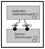
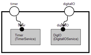
In addition to the actor containment hierarchies, layering provides another method to hierarchically structure a software system. Layering and actor hierarchies with port to port connections can be mixed on every level of granularity.
an actor class can define a Service Provision Point (SPP) to publish a specific service, defined by a protocol class
an actor class can define a Service Access Point (SAP) if it needs a service, defined by a protocol class
for a given actor hierarchy, a LayerConnection defines which SAP will be satisfied by (connected to) which SPP
For the graphical and textual notation refer to the following table:
| Graphical Notation | Textual Notation |
|---|---|
|
|
|
|
|
|
Definition from Wikipedia:
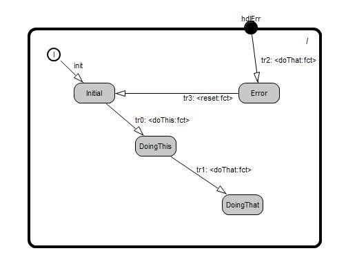
A finite-state machine (FSM) or finite-state automaton (plural: automata), or simply a state machine, is a mathematical model used to design computer programs and digital logic circuits. It is conceived as an abstract machine that can be in one of a finite number of states. The machine is in only one state at a time; the state it is in at any given time is called the current state. It can change from one state to another when initiated by a triggering event or condition, this is called a transition. A particular FSM is defined by a list of the possible states it can transition to from each state, and the triggering condition for each transition.
In ROOM each actor class can implement its behavior using a state machine. Events occurring at the end ports of an actor will be forwarded to and processed by the state machine. Events possibly trigger state transitions.
For event driven systems a finite state machine is ideal for processing the stream of events. Typically during processing new events are produced which are sent to peer actors.
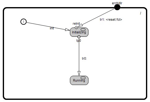
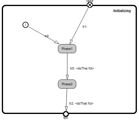
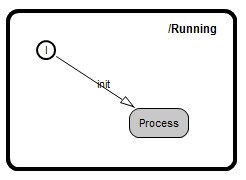
We distinguish flat and hierarchical state machines.
State machine execution begins at the top level by traversal of the initial transition. During traversal of a transition its (optional) action code is executed.
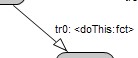
So called triggered transitions start at a state or a transition point. The simple most trigger is a pair of port (or SAP) and message.
For the following we will discuss hierarchical finite state machines, which include flat state machines as a special case.
Assume the state machine is in an arbitrary leaf state (states with no nested state machines). Then when an event occurs, a transition with a matching trigger is searched. This is done level by level from the state graph of the current state to the top level state graph. First all outgoing transitions are considered, then handler transitions. If no match was found this is repeated one level higher and so on to the top level. If no match is found at all, the event is discarded.
Then the transition which was triggered is traversed.
For any transition it can continue in several ways:
All this is looped until the new leaf state is reached.
We distinguish flat finite state machines (with just one level of hierarchy) and hierarchical ones.
The simpler flat finite state machines are composed of the elements shown following table:
| Element | Graphical Notation | Textual Notation |
|---|---|---|
State |
|
|
InitialPoint |
|
implicit |
TransitionPoint |
|
|
ChoicePoint |
|
|
Initial Transition |
|
|
Triggered Transition |
|
|
The hierarchical finite state machine adds the notion of a sub state machine nested in a state. A few modeling elements listed in table below are added to the set listed above.
| Element | Graphical Notation | Textual Notation |
|---|---|---|
State with sub state machine |
Parent State |
Sub state machine |
Entry Point |
In sub state machine |
|
Exit Point |
|
|